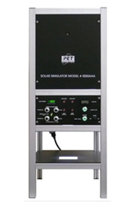
This site uses cookies to offer you a better browsing experience. By continuing to navigate through this site or by clicking Approve, you consent to the use of cookies on your device as described in our privacy notice.

Solar Simulators

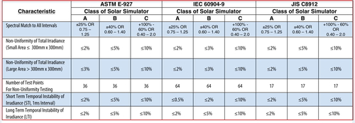
Photo Emission Tech., Inc., manufactures and markets cell testers and solar simulation systems that are also known as sun simulator that provide full spectrum light equivalent to the sunlight. The primary applications of these solar simulators are checking Photovoltaic Cell performance, materials testing, photo-lithography, cosmetic testing and in any other application where the effect of exposure to sun light needs to be studied, such as photochemistry/photobiology testing and environmental exposure testing. Seven standard solar simulators models are available for each class that serves these markets. Solar simulator systems can be manufactured with three different air mass (AM) filters: AM0, AM1 and AM1.5. These solar simulators meet Class A requirements of ASTM E927-2010, IEC60904-9 Edition 2.0 2007-10 and JIS C 8912-1998: amendment 1-2005 & Amendment 2-2011.

The ground level spectrum of natural sunlight is different for various locations on earth. The constituents of the atmosphere affect both absorption and scattering. Elevation is another factor that affects the ground level spectrum, since the elevation determines how far the sun's radiation must pass through the atmosphere. For any given location the distance the sun's radiation must travel through the atmosphere changes as the day progresses, due to the changing angle of the sun. With the sun directly overhead the direct radiation that passes through travels the shortest distance through earth's atmosphere to reach the earth. The spectrum of this radiation is referred to as "Air Mass 1 Direct" (AM1D). For standardization purposes sea level is used as a standard reference site. The global radiation with the sun overhead is referred to as "Air Mass 1 Global" (AM1G). The spectrum of sun's radiation in space does not pass through any air mass hence it is referred to as "Air Mass 0" (AM0).

Enquiry

Exposure Control

Each Solar Simulator has a shutter that can be operated manually from a switch on the front panel or remotely with a foot pedal. The shutter can also be programmed to open from 0.1 second to 999 seconds with a built in timer control.

Output Power

It is possible to factory set the system light output higher than one sun when the lamp is new. If the system output is higher than one sun, then the intensity control is used to adjust the system output at one sun. As the lamp ages, the intensity control can be adjusted to maintain one sun output.

Light Intensity & Control

The light intensity for all our Solar Simulators is one sun (1,000W/m2) ±20%. The intensity can be adjusted with the provided control on the front panel. The intensity adjustment is done by adjusting the control voltage to the Lamp Power Supply. Reducing the intensity below 80% is not recommended by this control method. The Lamp requires a certain minimum current to operate properly and provide stale spectrum. If testing needs to be done under intensities less than 0.8 suns (800W/m2) then we recommend using Neutral Density Filters (NDF) to control the intensity from 0-1,000W/m2, without compromising the spectrum of the light. Each system has a Constant Light Intensity Controller as a standard feature. This control system maintains a constant level of light intensity for long-term exposures.

Safety Interlocks

The Light Source unit has safety interlocks. The door for lamp replacement has an electrical interlock to shut down the system if the door is opened without turning the system power off. This prevents access to the lamp when it is on thus preventing operator exposure to the radiation and protects against inadvertent contact with the hot lamp. There is a thermal interlock that turns the lamp off in the event the temperature within the housing exceeds safe operating levels. In addition there is a safety interlock that turns the system power off in the event the cooling fan fails.

Lamp Aging

The xenon arc lamp should be replaced at the after the rated life has been reached to ensure spectral fidelity and proper level of intensity. The rated life of each lamp typically ranges between 1,000 – 1,500 hours. In our computer controlled Solar Simulator Systems, the lamp life is monitored and displayed and the software also displays a message to remind that the end of the rated lamp life has been reached. In Electro-Mechanical controlled Solar Simulators, the lamp life is monitored and displayed on an LCD Hour Meter. It serves as a convenient reminder of when the lamp should be replaced. PET Solar Simulators have a lamp alignment feature that allows the lamp to be aligned without the lamp being turned on. This feature makes it very easy to align the lamp for the best uniformity.

Features

PET Solar Simulators consist of a Light Source with a built-in Lamp Power Supply. The Solar Simulator has an ellipsoidal reflector that surrounds the lamp and collects most of the lamp output. The radiation from the lamp is focused onto an optical integrator that helps produce a uniform diverging beam. The beam is diverted 90° by a mirror onto a collimating lens. Special filters are placed between the mirror and the collimating lens to shape the radiation spectra to match various air masses. The output is a uniform beam that closely matches the sun's radiation spectra for a given air mass. Various models offer different areas of illumination. Each model can be manufactured to simulate the sun's radiation for different air masses.

The power supply unit provides constant electrical power to the xenon arc lamp. All of our systems come with a standard closed loop light intensity controller. This helps in assuring very stable light intensity. In addition the power supply unit houses control circuitry for several control features. Some of the control features are discussed here.

APPLICATIONS

  • Photovoltaic Cell Performance:
    • Determining electrical performance of photovoltaic cells
    • Comparison of cell characteristics among group of cells or different cell designs
    • Repeated measurement of the same cell to study life cycle performance changes
  • Photochemistry/Photobiology:
    • Testing sunscreen efficacy
    • Studying biological effects of solar radiation
  • Environmental Exposure Testing
    • Evaluating the effect of solar radiation on various materials and finishes
    • Accelerated testing for cross-linking of polymers and embrittlement of plastics
    • Testing for color fading of paints and fabrics
    • Qualifying and life-time testing of materials for space

Table: Solar Simulator International Standards Summary

In order to classify a Solar Simulator as a “Class A” system, it must meet all three requirements specified under Class A, i.e. the non-uniformity of the irradiance over the area of illumination must be ≤2%, and the Short Term Temporal Instability of irradiance must be ≤0.5% and the Long Term Temporal Instability (LTI) of irradiance must be ≤2%, and the spectral match in each wavelength interval must be ±25% or better. In addition, the total intensity must be 1,000W/m2 (100mW/cm2) for AM1.5G.
 

TYPICAL FINAL TEST REPORT

A report similar to the typical final test report shown below is delivered with each Cell Tester or Solar Simulator to certify that the Cell Tester or the Solar Simulator meets or exceeds all the criteria of the Class AAA requirements of ASTM E927-2010, IEC60904-9 Edition 2.0:2007-10 and JIS C 8912-1998: amendment 1-2005 & Amendment 2-2011AAA system. Pages 1 through 5 of Typical Final test report are included in the Final Test Report for each Solar Simulator shipped. Page 6 of the Typical final test Report is included in the Final Test Report for Solar Simulators with Touch Panel Controls and page 7 of the Typical Final Test report is included in the Final Test Report for each Cell Tester.

Contact Us at +9714 2152799

We can help you with a solution tailor to your specific need.