This site uses cookies to offer you a better browsing experience. By continuing to navigate through this site or by clicking Approve, you consent to the use of cookies on your device as described in our privacy notice.
Structural Engineering

Structural Engineering

The simplest mode is to use the hardware and backboard to build a structure.
Applying loads by hand and seeing how the structure reacts gives instant feedback and a great learning experience.
Using the display and visualisation software takes this learning experience to another dimension. Graphical display of bending moments, shear forces, deflections and reactions in response to a simulated load really bring these concepts to life. Displaying these simulations on the screen, overlaid with the physical model, and comparing the simulations with the hardware provides an unparalleled and totally unique teaching capability.
The software can also be used on its own without the hardware if desired.
The next stage is to add the optional instrumentation hardware package.
This enables loads to be applied to the structure from the computer, and actual reactions and displacements measured on the sophisticated sensors. Thus quantitative measurements of loads, displacements and reactions can be taken.
The sensors and actuators can also be used in a freeform mode to apply and measure responses to the user’s own structure.
Finally, it is possible to do a full computer simulation of the structures. Armfield provide models of the key structures, which can be run directly on a demonstration version of the professional software structural analysis package supplied.

Enquiry

Introduction

Modern structural engineering makes extensive use of computer programs to provide the detailed analysis, design and 3D modelling of structures. Once a structure becomes even slightly complex the calculations involved exceed what can be sensibly implemented using manual or spreadsheet calculations. Similarly modern teaching practice focuses on the use of these structural engineering analysis programs. Although these provide a superb numerical analysis facility, they rely totally on the user having an inherent understanding of the structure to be analysed. Unfortunately, this is not always the case. The analysis is only as good as the information provided and can do nothing to improve an inherently flawed concept (RIRO). Conventional structural engineering teaching equipment does little to provide this understanding, focusing on detailed analysis of simple situations, it makes no attempt to encourage the student to think of what really matters when designing or analysing structures. Armfield have teamed up with Dr David Brohn (who is also working with the Institution of Structural Engineers on this topic) to develop a range of hardware and software specifically to address this issue of understanding structural behaviour. The range of equipment enables a wide variety of structural models to be assembled and understood. It deliberately uses a series of elements, which provide an exaggerated response enabling the deflections to be visualised. Even the basic system without actuators or sensors can provide invaluable understanding of the structures just by pressing manually and observing the deflections. When coupled to the display software, the sensors, the actuators and the analysis software, the equipment provides an unsurpassed and unique learning experience.

Understanding Structural Behaviour ST10

ST10 includes:
Eight standard projects including cantilevers, beams and portal frames
Backboard matrix for building the physical structure model
Set of elements, supports and joints for the above range of structures to be implemented (many others can also be implemented)
32” High definition display with HDMI interface
Display and Visualisation software
RISA 2D models
Book “Understanding Structural Analysis” by Dr. David Brohn − Includes demo version of QSE Analysis software
Storage facility for all components
Capabilities can be extended by the addition of the Instrumentation Package ST11

Instrumentation Package ST11

ST11 comprises:
Deflection Sensor; Linear Actuator; Three Component Rigid Support Sensor; Two Component Pinned Support Sensor;
Simple Support Sensor, Interface Unit plus power supply and interconnecting cables; Software for Control and Instrumentation functions is supplied with ST10.
Note: Additional sensors and actuators can be added later.

Functions of the software

  • Contains presentations to introduce the concepts of bending moment, shear, deflections and reactions and their associated graphical representation on the structure diagram
  • When used in conjunction with the instrumentation hardware, the software controls the actuators and displays the outputs from the various sensors
  • In this mode the displayed diagrams relate to the actual load applied by the actuator, rather than a simulated load
  • Provides calibration for the sensors and screen

Technical Specifications

This is a highly modular system with almost an infinite range of possibilities.
To simplify purchasing, the components are available in a number of kits depending on requirements.

ST10 – Understanding Structural Behaviour

  • Comprises:
  • Backboard
  • Set of elements, supports and joints for the above range of structures to be implemented (Many others can also be implemented)
  • 32” high-definition display with HDMI interface
  • Display and visualisation software
  • RISA 2D models
  • Book Understanding Structural Analysis by Dr David Brohn
  • Includes demo version of QSE analysis software
  • Storage facility for all components

ST11 Instrumentation Package (for use with ST10)

  • Comprises:
  • Deflection sensor
  • Linear actuator
  • Three-component rigid support sensor
  • Two-component pinned support sensor
  • Simple support sensor
  • Interface unit plus power supply and interconnecting cables
  • Software for control and instrumentation functions is supplied with ST10

Note: Additional sensors and actuators can be added later.Requires ST10 Understanding Structural Behaviour

Features & Benefits

  • Intuitive design providing great touch and feel
  • Carbon fibre elements provide exaggerated response for enhanced visualisation
  • Carbon fibre elements also provide negligible plastic deformation for long life and repeatability
  • Fully integrated hardware and software display
  • Includes eight standard projects including cantilevers, beams and portal frames
  • Wide range of additional structures can be constructed from simple components
  • Compare computer simulations with actual responses
  • Sensor and instrumentation package
  • Supplied with the textbook Understanding Structural Behaviour

Features

  • Educational tool aimed at giving students an understanding of how structures behave
  • Eight standard structure projects can be built up on the widescreen display. The software calculates the simulated performance of the structure, ie deflection, moment force diagram, shear force diagram, and reactions.
  • These diagrams are displayed directly behind the physical model of the structure at the same size of the model and so can be directly related to the responses obtained by applying manual stimuli
  • Supplied with a selection of elements of different lengths, fixed and pinned joints, and fixed, pinned and slide supports, allowing a wide range of physical structures to be assembled
  • Carbon fibre elements provide an exaggerated bending response to aid visualisation and understanding
  • An optional sensor and instrumentation package enables loads to be applied from the software, and the resulting reactions and deflections to be measured and displayed on the screen
  • Supplied with the textbook Understanding Structural Analysis by Dr David Brohn

Display & Visuaisation Software

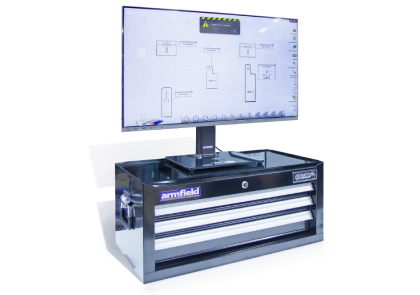
This software is a fundamental part of the Understanding Structural Behaviour concept, and works in conjunction with the hardware to demonstrate and help that understanding.
For a number of predefined structures it is possible to perform an immediate interactive simulation of the effect of loading on the structure. Loads can be simulated using the computer mouse and the shear force diagrams, moment diagrams, deflections and reactions are shown graphically and updated continually as the load is varied.

Scaling of displays

The deflection diagrams, moment diagrams and shear force diagrams can now be individually scaled. This allows the data to be displayed more clearly for a wide range of different conditions.
For example, large deflections can be scaled down at the same time as small moment forces being scaled up.One drawer is available for the ST11 instrumentation option.
When combining the hardware and software, the diagrams are displayed immediately behind the structure and are therefore directly related to it.


Two new structures introduced

  • Cantilever beam
  • Simply supported beam

These two basic structures offer an introductory level to the teaching of structural engineering, and can be used to introduce basic concepts of reactions, shear forces and moments.

Functions of the software

− Display the structure to be evaluated to aid correct assembly
− Display the structure in diagrammatic form and as typical pictorial implementation of the structure. This has been proven to be a powerful aid to student understanding
− Gives a graphical representation of bending moments, shear, deflection and reaction in response to simulated loads

 
  • Contains presentations to introduce the concepts of bending moment, shear, deflections and reactions and their associated graphical representation on the structure diagram
  • In this mode the displayed diagrams relate to the actual load applied by the actuator, rather than a simulated load
  • When used in conjunction with the instrumentation hardware, the software controls the actuators and displays the outputs from the various sensors
  • Provides calibration for the sensors and screen

Analysis software

Armfield supply software models for all the predefined structures, which can be analysed in a freely available demonstration version of a professional modelling software package. Armfield also supply the demonstration version of this package.
From this starting point, users can analyse their own models and structures, either using the Armfield components, or using the software. The software enables any beam material, size, thickness, strength etc to be defined and analysed.
A second analysis software package (QSE Space planeframe) is also available with the supplied textbook, Understanding Structural Analysis.
Note: For support of both these analysis software packages, the suppliers should be contacted directly.


Instrumentation Package

The instrumentation package includes a range of sensors and actuators used to stress and measure the performance of the structural hardware. Components available are:

Three Component Rigid Support Sensor – ST11-1

  • This is used instead of a fixed rigid support with the structural hardware. It measures both the vertical reaction at the joint (in the direction of the element, equivalent to the tension or compression), the orthogonal reaction at the joint and the moment reaction.

Two Component Pinned Support Sensor – ST11-2

  • This is used instead of a fixed pinned support with the structural hardware. It measures both the horizontal and vertical element reaction at the joint.

Deflection sensor – ST11-3

  • Used to measure the deflection of the beam at a grid point.

Simple Support Sensor – ST11-4

  • Used instead of a simple slide support, and measures the reaction on the support.

Linear Actuator – ST11-5

Complete with sensor to measure the force (load) generated by the actuator to reach the requested deflection.


Interface Module – ST11-6

  • Provides the interface between the sensors and computer by a standard USB2 interface. It also includes a universal input power supply and interconnecting cables.


The sensors and actuators are connected to the interface unit and to each other using linking cables in a chain configuration. They can be connected anywhere on the chain and multiple components of the same type can be configured in the same system.
Additional sensors and actuators can be bought individually and added at a later date if required.

Technical Resources

ST Series - Structural Engineering Datasheet

Datasheet

VIEW

Contact Us at +9714 2152799

We can help you with a solution tailor to your specific need.